Shadows
Although this is the last topic in this module, shadows contribute a lot to the visual effect of the scene. Through shadows humans distinguish more clearly movement and depth of objects. Shadows are important, but also require more complexity to get right. Compared to light calculations, where we can have some (often quite a lot) deviation from reality, for shadows it is more easily detectable if something is wrong. There are a number of techniques that can be used to create shadows for the objects. Through history some have been more popular than others. In this topic we will see real-time techniques shadow mapping and shadow volume, also known as stencil shadows.
First let us think about what shadows actually are. They indicate the absence of some direct light. Another object is in the way of our point in shadow and the light source. In reality the light sources have some area. We use differently shaped lamps to distribute the light from the bulb around. Because of that area, there will be parts of our scene that will be illuminated by only a portion of the light. If you have an object in front of an area light source, then depending on the distance and areas, some places can be in complete shadow (umbra), some can be in half-shadow (penumbra, antumbra).
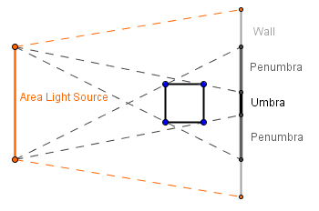
If you were to move the wall further away, then the umbra would not reach it. The area, where the penumbras meet would be called antumbra.
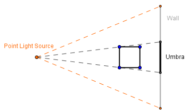
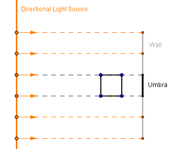
Unfortunately, if we are modeling the scene with a point or directional light source, then by themselves they would only generate the umbra. For the point light source the area is infinitely small, so all other objects will be bigger from it. This means that if they cover the light source, they will cover it fully. For the directional light source, the area is infinite and light only travels from it in a single direction. If we were to model it in a way, where light could travel in all directions (as is the case with area lights), then everything would be always lit and there would not be a shadow. So we are left only with this single direction of light, it is easy to see that it also casts only the umbra.
 |
 |
So, because our light sources are modeled this way, they only cast a hard shadow. For a more realistic effect, there are a variety of techniques that try to blur the edges of umbra to create an illusion of penumbra or antumbra.
Definitions we just covered:
- Umbra – Full shadow.
- Penumbra – Half-shadow formed in the partially shadowed area.
- Antumbra – Half-shadow formed, when different penumbras meet.
- Hard shadow – Shadow with hard edges, the umbra.
- Soft shadow – Shadow with soft edges.
Global Illumination Shadows
Well, in the global illumination we often can get realistic shadows with little effort. In order to estimate, where the light is travelling, we already are taking into account the scene geometry. Let us look closer at path tracing. Previously we applied a lighting model directly in all of the hit points of rays. This ignores the possibility that the hit point might not be directly visible from the light source. So, in order to find out if that is the case, we can send another ray directly into the light from the hit point. If it hits the light source, the point can have a light calculation applied on it for that light source. If it hits something else, then the point will be in the shadow.
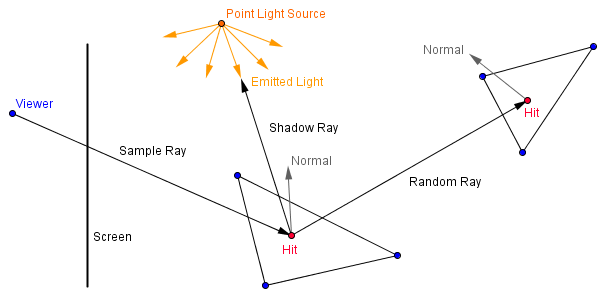
When we are modeling area light sources (which in the case of path tracing would be a good idea to do), then we can shoot a couple of rays to random points on the area of the light source. We are averaging the different frames together, so a few random rays each iteration will converge into a realistic shadow.
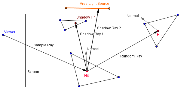
On the right there is an extension of the path tracer from the last topic, that now shoots 4 shadow rays into random positions on the 4 quarters of the area light source. Depending on how many of the shadow rays actually hit the light source, the light contribution from that light source will be accounted.
You can see that there will be an umbra and a penumbra of the cube on the floor.
Shadow Mapping
For your standard graphics pipeline rendering way, shadow mapping is currently quite a popular technique. We again want to know, if a fragment we are rendering, is in the shadow or not. Is there something between our fragment and the light source? This is same as asking, is that point visible from the light source or is it occluded by some other object?
We can find that out, if we render our scene from the light source. That will create the depth buffer as seen from there. After this we can check for each fragment, is the value inside the depth buffer less than the value our current point would have. This gives us an easy way to find occluded fragments, but it does have some problems.
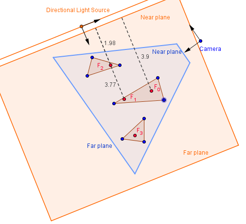
First, we need to render from the light source using a camera, whose view volume corresponds with the volume that is illuminated by that light source. Generally that would need to include the entire view volume of our normal camera. Also, depending on the type of the light source, we would need to use different projections. For a directional light source, we can use an orthographic camera, because we want to know the nearest objects to the near plane.
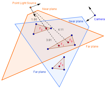
For a point light source, we need a perspective camera, because we want the distances to the point. If the point light source is inside our view volume, then we would need 6 perspective projections, a cube camera, to render each side of the point light source.
As you can see from the image above, specifying too low far plane will result in some of the fragments (currently $F_3$) not being visible from the light source. This means that if we check for something behind them, we will not get a shadow cast from them.
Second problem is that we get a skewed resolution for the shadow map (the depth buffer rendered from the light source). Rendering normally from the light source, creates us a buffer that has resolutions of objects corresponding to the location of the light source. If we render from the normal camera, then we want more resolution for the objects closer to it and less for the objects further away. This resolution is not conveyed in the shadow map and thus we get aliasing around the edges of the shadows. Although, there are methods that try to improve this using trapezoidal shadow maps.
On the example to the right, we have a point light source in the middle of the scene. There are 6 perspective cameras (a cube camera) that render the scene from that point. For each fragment rendered normally, one of those 6 depth buffers is sampled and compared against the current fragment's position in that camera's projection.
You can change the resolution of the 6 cameras and see that the higher resolution does effect the shadow quality, but because of the differences in the resolutions of the shadow maps and the final render, we do have aliasing on the edges of shadows.
Shadow mapping is currently popular, because newer versions of OpenGL support that in the hardware level. There are specific samplers for sampling a depth texture and doing the comparison.
Shadow Volume
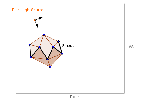
Another technique, that's variant was popularized by Doom 3 in 2004, is called shadow volume or stencil shadows. Main idea is to actually construct the volume that would encapsulate the shadow for all of the objects in the scene. In order to do that, first one has to find the silhouette for all the objects. This means finding edges, that have one face facing towards the light source and another away from it.
Those edges will serve as the perimeter, where vertices towards the light source will stay where they are, but vertices away from the light source should be extruded far away. When doing this, we also need to construct the side of the shadow volume. We create duplicates of the vertices on the silhouette line and extrude the duplicates. Then we create faces in between those pairs of silhouette vertices.
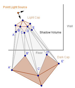
The three parts of this shadow volume can be called the light cap, dark cap and the sides. So, how far away would we need to move the dark cap? The answer is to infinity. Mathematically this means that we set the fourth value for those points in the homogeneous coordinates to 0. This effectively would send the points to infinity: $(x, y, z, 0) = (\frac{x}{0}, \frac{y}{0}, \frac{z}{0}) = (\infty, \infty, \infty)$. You may wonder that, where will that point then be drawn? The thing is that even if something is set to be in infinity (very far away), we can still have a point on the 2D projection of it. You can think about firing a ray gun, that shoots the ray in a straight line to infinity. You probably will see the ray approach some specific point in your perspective. If someone fires the same gun so that the ray passes you from left to right, then you will see the beam passing your entire perspective.
Mathematically it is actually the same as projecting on a sphere around the viewer. This is why people used to think that distant stars (that are very far away) rotate on a sphere that encapsulates the Earth.
What we here try to achieve, is that the shadow volume should be rasterized as much as we can possibly see it. If we move it only a finite amount, then it may happen that it will not encapsulate some of the objects in our scene. Furthermore, we do not want it clipped by our far plane. This means that we would also need to move our far plane to infinity. Let us see what happens with the projection matrix, if we do that. The perspective projection matrix from the Projections topic was:
$P = \left( \begin{array}{cc}
\dfrac{1}{aspectRatio \cdot tan(\frac{\alpha}{2})} & 0 & 0 & 0 \\
0 & \dfrac{1}{tan(\frac{\alpha}{2})} & 0 & 0 \\
0 & 0 & \frac{near + far}{near - far} & \frac{- 2 \cdot far \cdot near }{near - far} \\
0 & 0 & -1 & 0
\end{array} \right)
$
As we can see, the far plane plays a role only in the elements of the third row.
$\lim\limits_{far \to \infty}{-\dfrac{far + near}{far - near}} = \lim\limits_{far \to \infty}{-\dfrac{\frac{far}{far} + \frac{near}{far}}{\frac{far}{far} - \frac{near}{far}}} = {-\dfrac{1 + 0}{1 - 0}} = -1$
$\lim\limits_{far \to \infty}{-\dfrac{2 \cdot far \cdot near}{far - near}} = \lim\limits_{far \to \infty}{-\dfrac{\frac{2 \cdot far \cdot near}{far}}{\frac{far}{far} - \frac{near}{far}}} = {-\dfrac{2 \cdot near}{1 - 0}} = -2 \cdot near$
So, if we use a projection matrix with those elements, then we will not have far plane clipping anymore.
$P_{inf} = \left( \begin{array}{cc}
\dfrac{1}{aspectRatio \cdot tan(\frac{\alpha}{2})} & 0 & 0 & 0 \\
0 & \dfrac{1}{tan(\frac{\alpha}{2})} & 0 & 0 \\
0 & 0 & -1 & -2 \cdot near \\
0 & 0 & -1 & 0
\end{array} \right)
$
After all that we should have the correct shadow volumes for each object rendered from the object to infinity. In order to avoid z-fighting, the light cap should be shrunk a bit from the actual boundary of the object.
The traditional shadow volume algorithm now determines the shadows with the use of a stencil buffer. That is a buffer, where we can write custom values depending on the objects currently being rendered. It can be used to afterwards render only those fragments that have a specific value in the buffer. What we need to now is:
- Render the scene normally, but with only ambient light.
- Enable the stencil buffer, disable writing to the depth and color buffers.
- Set the stencil to always pass.
- Set the stencil function to increment the values in the buffer.
- Enable back face culling.
- Render the shadow volumes.
- Set the stencil function to decrease the values in the buffer.
- Enable front face culling.
- Render the shadow volumes.
- Enable back face culling again.
- Enable writing to the depth and color buffers.
- Set the stencil to pass only, when there is a 0 in the buffer.
- Enable blending and set blending factors to $sourceFactor = 1$, $destFactor = 1$.
- Render the scene normally, but only with diffuse and specular lighting.
To sum this up, we just increase the values in the stencil, whenever we enter a new shadow volume; we decrease the values in the stencil, whenever we exit a shadow volume. If we are left with 0, then that fragment is not in a shadow. We add the diffuse and specular only to the fragments that have a 0 in the stencil buffer.
On the right you can see an example of that being done. You can see the shadow volumes (that have light green surface normals drawn on them). You can see the dark cap of the back wall if you enable front face culling. It is the uniform blue area. Light caps are colored with uniform yellow and sides have a gradient between yellow and blue.
As you can see, the shadows have a more finer edge than with shadow mapping. Although this will depend on the finesse of the geometry (because the shadow volumes are constructed from it) and it is also quite resource consuming: we are doing many rendering passes with full resolutions; we more than duplicate the vertex counts; all shadow volumes need to be recomputed each frame.
You can read more about shadow volumes and get a more detailed description here.