Environment Mapping
Before we talk about environment mapping, let us first think what we would mean by the environment. So far the examples have mostly been with a black background, as if the objects were all located in empty space. This is usually not the case and we want our scene to be located in either a closed environment (e.g. in a room) or in open environment (e.g. outside, with a visible sky). As it turns out it is more efficient to create an illusion of an open environment, rather than having an actual simulation of the Earth, stars, the Sun or the Moon, mountains or whatever we want to see in the distance.
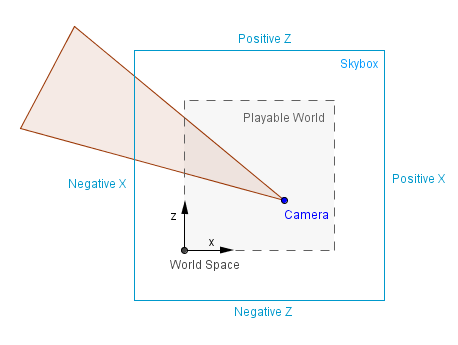
Imagine that there is a mountain in the distance inside a game. A mountain that the player can never travel to, because it is so far away. Modeling the actual geometry of that mountain and then rendering it at some really narrow range of angles all the time would take resources of the GPU. It is much more efficient and quite effective to just have a prerendered image of that mountain to display. The key points here are that the player should never be able to reach that background and that there will always be enough distance between the player and the background. If these requirements are met, we can create the background as it would seem from the center of the scene. Then we can use that background as a texture in either a cube or a sphere (or hemisphere). This is usually called a skybox or a skydome. Because the objects are very far away, moving the camera around has in reality a very small change in the angle on which we look at those objects. So a stationary skybox, where there will be no change at all, kind of approximates that effect.
Definitions:
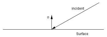
- Reflection – operation where an incident vector (incoming) is reflected from the surface normal, resulting in a reflected (outgoing) vector.
- Skybox – large textured box around the world for displaying very distant objects that can not be reached.
- Skydome – large textured sphere or a hemisphere around the world for displaying very distant objects that can not be reached.
- Cube mapping – idea of mapping all of the surroundings to the six faces of a cube.
- Sphere mapping – idea of mapping all of the surroundings to a sphere.
Cube Map
The skybox example above is perhaps the most simplest case of the cube mapping technique. The images that are mapped to the faces of the skybox cube can be constructed so that there is a camera in the center of the skybox that takes 6 snapshots with a 90° field of view. This of course creates distorted images, but the actual perspective projection will undo that distortion and the viewer will see the objects in the distance correctly.
That is already an environment mapping, although the actual environment may have or may have not been there. The images in the skybox could have been drawn by hand, generated procedurally, taken with a real camera in the real world or rendered in an environment that is not rendered later on.
Another thing that we can do with environment mapping is to create reflections. We saw before that there were diffuse surfaces that almost always absorbed all the incoming light (and emitting some of it in a random angle). There were also specularly reflective surfaces, that reflected the specular highlight of the light source. This is an approximation because, as we know, light does not come from only the light source. Light bounces around in our environment and based on it reaches different parts of our scene at different angles. In order to realistically model that, there are global illumination techniques, that we will see later on. Currently we are interested in creating one reflective object that would know about the light coming in from the environment.
Let us assume it is a reflective sphere and all we have in our scene is that sphere, the skybox and the camera. We can find the vector coming from the camera to a fragment of the sphere. We also know the surface normal (interpolated normal in the case of the sphere) at that fragment. Knowing those, we can find the reflected vector as follows:
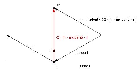
We know the incident vector and the surface normal.
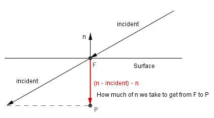
Let us take the dot product between those. We will get the scalar projection that shows us how much of the normal we need to take if we were to project the incident vector to the normal line.
Now, this vector itself does not help us. We will need 2 times the opposite vector.
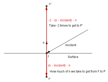
Here we can already see that if we were to add the incident vector together with -2 times the scalar projection of it, we will get the reflected vector.
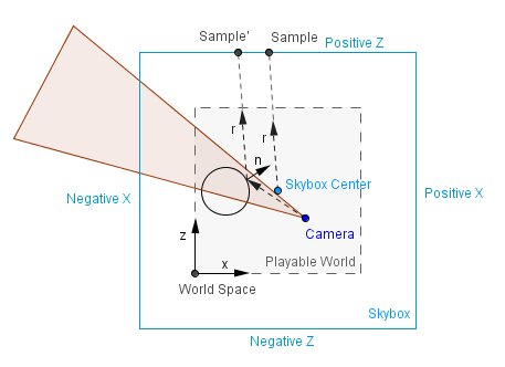
This is quite efficient to find the reflection vector. In global illumination techniques we should now try to find what surfaces this vector will intersect with first. But with cube mapping, as is the case with our current skybox example, we do not have to calculate the exact intersections. We can approximate that the fragment is always located in the center of the cube. It is so, assuming that objects in our skybox are infinitely far away. If we assume that the fragment is in the center, then we can just look at the component of the reflection vector with the greatest magnitude, to determine the face it will hit. The exact hit coordinates will be the other two component, scaled and shifted to texture coordinates $[-1, 1] \rightarrow [0, 1]$.
Think about the 2D case on the right (which might just be a slice from the 3D world, where y coordinates are all the same). Assume that the reflected vector is something like $r = (-0.08, 0, 1.27)$, when normalized, it becomes $r_{norm} = (-0.063, 0, 0.998)$. We can see that the z component has the largest magnitude, it has also the positive value, so we pick the Positive Z face.
We can then use the -0.08 and 0 to find the correct place to sample. After the mapping, UV coordinates will be $(0.047, 0.5)$, this is where we will sample from the texture on the Positive Z face.
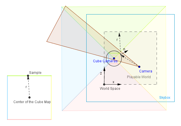
Now, this works really well if our scene is static and we do not have any other objects in our scene. If we have some other objects in the scene, that need to be reflected from our reflective sphere also, then we need to use another cube map and update it.
Cube map generation here will work exactly as described earlier, we need to take 6 pictures and use those as the textures. You can use one camera, orient it with different axes, or use 6 different cameras. In either case you need to render from inside our reflective object to a buffer / texture. Logically this will consume more GPU resources than a static cube map. It is safe to assume that it will consume at least 6 times more resources than one rendering pass.
On the other hand it will allow you to reflect your moving geometry and scene accurately. There is one defect though, it can not reflect accurately objects that are themselves reflective. This would include recursive rendering and in the worse case could take a lot of passes to complete (if at all). Much better approach for a multi-hop reflectivity would be techniques based on ray tracing, that we will see later.
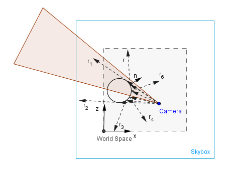
You can play around with a dynamic cube map in the example on the right.
Sphere Map
Historically before cube mapping there was first sphere mapping. It consisted of having an image of the environment as if it were reflected off a reflective sphere infinitely far from the camera. This means that almost the entire environment will be mapped to a spherical image from which to sample. There are some pros and cons with that.
Pros:
- Entire environment is mapped to one image, we can sample from it, instead of a cube.
- The center, where the reflection angle is near 0°, has good resolution.
Cons:
- There is a blind spot exactly behind the sphere.
- The edges, where the reflection angle is near 90°, may have aliasing, because we do not have enough pixels to hold the data.
- Sphere map itself is difficult to generate: for a real photograph you need to have 360° lens and the camera would be also in the image; for programmatical generation you need a reflective sphere (with cube mapping for example).
- For a dynamic sphere map you would need to generate it again, just like with the cube map.
- Because of the different resolution, it is dependent on the camera position. If the camera position changes, you would need to regenerate it to avoid aliasing.
As you can see on the right, when we disable automatic sphere map generation and then rotate 180°, we can see the quality decrease, increase in distortion, and a blind spot exactly behind the sphere which we mapped.