Global Illumination
While the techniques we have seen so far are quick to compute (with the exception of ray tracing), often times they can seem a bit unrealistic. With textures and effects one could create an experience that will be sufficient for some people. However, one aspect that has been missing is global illumination. Currently we have been dealing with local illumination, which means that each surface is illuminated only by the light sources. In reality the light bounces around in the environment and a surface is actually illuminated from all directions and by different wavelengths of light.
That is why the Cornell Box scene is often used to model the effects of global illumination. The red and green walls will reflect red and green light to the floor, ceiling and objects in the middle. Furthermore, the floor will also reflect white light to the objects from the bottom. Previously we approximated this with an ambient light parameter, which was often constant. Now we can try to see, if we could actually find out what light and from where is illuminating the surfaces indirectly.
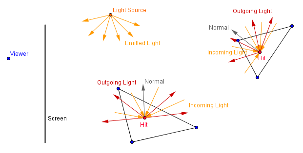
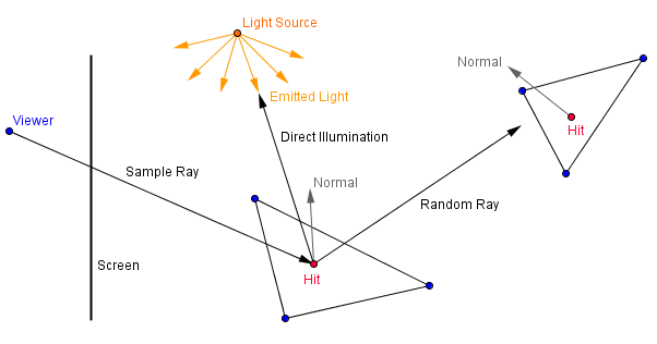
This idea is summed up via the rendering equation. Material color is affected by the light coming in from all of the directions along the hemisphere of the surface (around the surface normal). Depending on the surface properties (how much diffuse, how much specular – usually this and more is described via a specific bidirectional reflectance distribution function). If we have a totally diffuse surface and a point light source, then this idea could be described with the following image.
Definitions:
- Local illumination – idea that objects are only illuminated directly by the light sources
- Global illumination – idea that objects do not only reflect light to the viewer, but also to other objects
Path Tracing
We can not calculate the infinite integral in the rendering equation directly. That means that we can not sample infinitely many directions in order to find out the exact and correct color of our material. Path tracing will try to estimate that color by sampling in a random direction, sending many such rays per pixel and averaging the result. There are actually several variants of path tracing, some are more optimal and converge sooner then others.
The basic idea, however, can be described as follows:
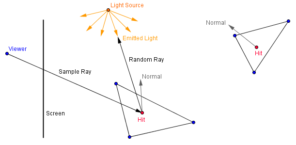
- Shoot a ray through the pixel into the scene, find the first intersection.
- Reflect the ray from the hit point to a random direction.
- If ray hits the light source, return the emittance of the light source.
- Repeat the steps 2-3 some number of times (could even be a random number of times).
- If the ray did not hit the light source during those steps, do not consider that ray.
- If the ray hit the light source, then recurse back and take the BRDF-s of the surfaces into account.
- Repeat the steps 1-6 a large number of times per pixel.
- Average all the rays that hit the light source.
So this means that first we just shoot one ray through the pixel. We will bounce it in a random direction. If it hits the light source, then we consider the illumination originating from the light source. As you remember, point lights and directional lights are not exactly realistic, for a correct result you should have an area light source that emits a large number of luminance.
Then we shoot another ray and bounce it in a random direction. This ray may not hit anything at all and will not be considered in the total average for the pixel in hand.
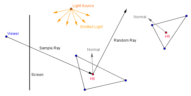
Third ray could hit some other material. If that happens, you can randomly decide if you will stop and consider that ray as a miss. Or you will bounce it again in a random direction and consider all of the cases it might hit or miss.
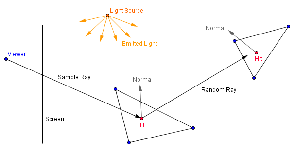
If you repeat this a large number of times per pixel and average the result, then the final image will approximate a realistic result.
Because many of the rays will be misses, this is not a that valid approach for a real-time rendering. However, we could consider following optimizations:
- Have a closed scene, a ray will always hit something.
- After a number of bounces, direct the ray towards the light source.
- Alternatively, in each hit, consider the local illumination of the hit point as the emittance originating from the material (add it to the overall result).
The last idea is illustrated as:
One sample for the ray going through the pixel to a scene with diffuse surfaces would be:
$color = matColor_1 \cdot lightDir_1 \cdot normal_1 + brdf_1 \cdot (matColor_2 \cdot lightDir_2 \cdot normal_2 + brdf_2 \cdot (matColor_2 \cdot lightDir_2 \cdot normal_2 + ... ))$
where the $brdf_i$ would be $matColor_i \cdot randomReflectDir_i \cdot normal_i$ for diffuse surfaces.
That is also implemented in the example on the right. That example might also be slow for some GPU-s, because ray tracing itself is slow. I am currently not using any data structures or bounding volumes. You can specify the number of bounces each ray makes.
As you can see, with 0 bounces, the scene is exactly like it would be rendered via the standard graphics pipeline, ie has only local illumination. With 1 bounce you should see the red and green colors reflected to the ceiling, floor, back wall and the sphere in the middle. Notice that the sphere is grayish from the bottom, because the floor on the bottom has originally gray color. Now, if you specify 2 bounces, then the sphere will also be red and green from the bottom, because now the floor color is taken into account together with 1 bounce of indirect illumination.
You can read more about the different ideas behind path tracing in the this article.
Photon Mapping
There are more algorithms for global illumination like radiosity and photon mapping. Path tracing that we just saw, takes a lot of passes to converge to a view dependent render. Photon mapping tries to solve this via two steps.
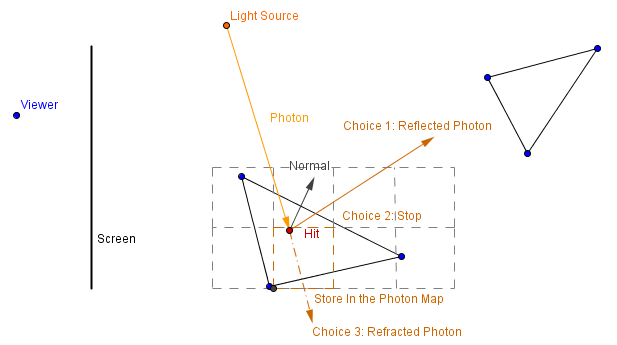
In the first step photons are sent out from the light sources. Upon intersection with a material, the photons have 3 choices:
- They are absorbed by the material, resulting in direct illumination.
- They are reflected off the material, resulting in indirect illumination for another object.
- They are refracted into or through the material, resulting in a caustic effect.
There are usually 2 spatial maps that store the photons. One for the global light and another for caustic effects. The photon map can be any data structure that allows fast nearest neighbour searching (like a K-D tree for example). Then a photon intersects a surface, the intensity if carries and the direction must be stored in one of the maps.
Such creation of the photon map can be done prior to real-time rendering. Realistic result is approximated by the number of photons sent from the light source.
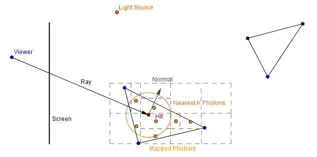
In the second pass a ray tracing rendering is done. When a ray intersects a surface, we can find a number of nearest stored photons. Then we can find a minimal sphere that covers those photons. The color of the material is the sum of the contributions from all of the nearest photons. To find a contribution for one photon, the BRDF between the photon's direction and the surface normal should be multiplied by the ratio between photon's intensity and the area of the sphere.
The idea is that we have some nearest photons that each stores some direction and intensity of light. All of them need to approximate the total illumination inside some area (the sphere). Depending on the photon's direction, it will have a different affect on the material.
This will find a good approximation for diffuse surfaces and caustics. For specular reflections that are view dependent and direct illumination, rays should be traced to light sources. Indirect illumination will be approximated from the photons in the pre-computer photon map.