Shading and Lighting
So far we have looked at geometry, transformations, projections. Those are all done in the vertex shader. Our examples have been white wireframes of the geometry. Now we will proceed to fragment shader, where the geometry has been rasterized and we can calculate the color our pixels should have. This is the main job of the fragment shader - to give out a color value for a pixel. In OpenGL the fragment shader gets, among other values, the gl_FragCoord value as input. This value is the coordinate in the screen space (also called window space).
Usually with basic 3D geometry we do not care that much about the screen space coordinate. Rather we are interested in values sent directly or interpolated from the vertex shader. This is because with vertices we can also send a color value and / or a surface normal from our program code. We do not know how many pixels are rasterized between the vertices, but we can interpolate values between them.
There are different techniques on how to assign a color to the rasterized pixels. In this chapter we will take a look at those techniques and see the differences between them.
Definitions:
- Shading model – technique that defines when and where do we calculate the components needed for light calculations.
- Lighting model – technique that defines how do we calculate the final color given all the components required for it.
- Material properties – properties of the material that determine how much an object with this material reflects a light from different channels.
- Light properties – properties of a light source that determine how much this light source emits light from different channels.
- Point light source – a light source where light is originating from a single point in space.
- Directional light source – a light source that defines light originating from a single direction in all of the space.
Shading Models
There are three main shading models that are used for different results: flat shading; Gouraud shading; Phong shading.
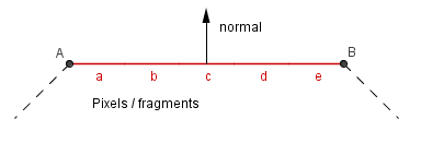
Flat Shading (per polygon)
This is the most simple and efficient way to specify color for an object. It defines a single color for a face. Implementations of it may vary, but the main idea is that we use only one surface normal per polygon. The color itself is uniform (unchanging) on that polygon.
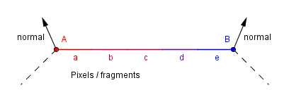
Gouraud Shading (per vertex)
This was invented as an improvement to allow for more smooth transitions of the color on round objects. Main idea is that there is a different normal per vertex and the color is calculated in the vertex shader. That color is then interpolated over the polygon. Because there are less vertices then there are fragments, then calculating the color per vertex and interpolating it, is more efficient than calculating it per fragment.
This approach handles badly materials that have a specular reflection. This reflection might occur inside the polygon, but not on any of the vertices. Thus this shading would not show it, if it does not happen to be on the vertex.
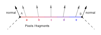
Phong Shading (per fragment)
This was another improvement in order to account for the specular reflection. Main idea is that the normal from the vertices is interpolated. Color is calculated per fragment, taking into account the interpolated normal. For an approximation of a sphere, this is quite ideal, because the interpolated normals would be exactly those that a perfect sphere would have. Because the color is calculated based on the normals, it will be calculated as if it were a perfect sphere.
On the right there is an example with all three shadings. Those shapes have only the diffuse reflection (no specular). As you can see there are still quite noticeable differences with the sphere. For the cube, there are actually 24 vertices. Each face has its own 4 with normals pointing to the same direction as the surface normal. In that case there is no difference (as far as the result is concerned) which shading is used.
Next we will look how is the actual color determined. It does not matter which shading is used as long as we have a surface normal, material properties, light source properties and the light direction.
Lambert Lighting Model
Before we look at the actual reflection of light from a surface, let us define a type of light source. Directional light source is a light source, that defines the light coming from a single direction. This is an approximation of reality, because it would assume an existence of an infinitely wide and tall object that emits light. Still, we are quite used to think of sunlight as directional light. The Sun is so big compared to earth, that in a visible area the angles of rays do not differ a noticeable amount.
Now, we are given a direction from where the light is coming from and some sort of a surface. Diffuse surfaces have the property to diffuse reflected light around. Light will enter the surface, bounce around there and then exit in a random direction. Or you can think that an atom will absorb the photon and after some time emits another photon to a different direction. Because of the diffusion of light, it does not matter at which angle we look at the material. All that matters is on which angle the light actually reaches the material.
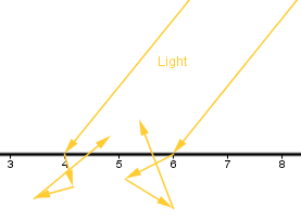
This is because the amount of light reaching one surface unit will be higher if the light is coming from a more perpendicular angle. If the light is coming from a grazing angle, then the same amount of light will cover a much larger area and thus a surface unit will receive less light.
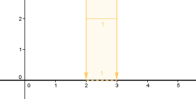 |
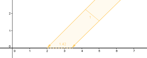 |
As you can see, the amount of light received and thus reflected is directly related to the angle between the surface and the light direction.
This is the place where we will need a surface normal. The cosine of the angle between the surface normal and the direction towards the light will directly give us the illumination percentage. If the cosine is 1, there is a 0-degree angle, and a surface unit will receive 100% light. If the angle is 30°, the cosine will be approximately 0.87, and a surface unit will receive 87% of the light. If the angle is 45°, we have around 71%.
Now, does this mean that we would have to calculate the cosine function in the fragment shader when coloring every pixel? Would not calculating the cosine function be quite slow?
Luckily, we can calculate the cosine in another way. As you remember, the dot product was geometrically defined as:
$v \cdot u = |v| \cdot |u| \cdot cos(∠uv)$,
but there is another, an algebraic definition for it:
$v \cdot u = \sum_{i=0}^{n} v_i \cdot u_i$.
If we are dealing with normalized vectors, then we can directly find out the cosine between them by just taking the algebraic dot product. So, we have to make sure our surface normal and the light source direction are normalized. Another thing to notice is, that because the cosine is negative for larger angles, we want to use only the positive values of the cosine. Otherwise we would subtract the light, if the light source is on the other side of the material. This becomes even more important when we add other terms to the equation.
This is the main idea behind the Lambert lighting model that models the diffuse reflection of light. Now, in order to determine the actual color, we need to know two things:
- What is the color of the light emitted from the light source?
- What colors are reflected from the surface?
In computer graphics we usually define our colors by three channels: red, green and blue. So we will have 3 terms for each of those channels for both the light source and the surface material. The final color computed in the fragment shader would be like this:
$red = M_{diffuseR} \cdot L_{diffuseR} \cdot \max(normal \cdot light,\;0)$
$green = M_{diffuseG} \cdot L_{diffuseG} \cdot \max(normal \cdot light,\;0)$
$blue = M_{diffuseB} \cdot L_{diffuseB} \cdot \max(normal \cdot light,\;0)$
Here the value $M_{diffuseR}$ would be the percentage of red light this material will reflect. The value $L_{diffuseR}$ will be the percentage of red light the light source emits.
In reality there are very few surfaces that are almost completely diffusely reflective. Examples would include the surface of the Moon, chalk, matte paper.
This model is the one used in the example in the Shading Models paragraph.
Ambient Light
The cubes and spheres shown before kind of appear to be in space. The non-illuminated sides of it are totally in darkness. In reality this is not the case, there is almost always some light coming from every direction. That is because light will reflect from nearby surfaces, bounce around and reaches the area not directly illuminated.
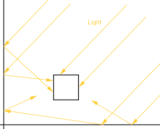
This is called indirect illumination and is one of the things that global illumination techniques try to do accurately, which may be computationally quite expensive. In our simple model we can do a very rough approximation and just add an ambient term to the reflected intensity. That way the non-illuminated areas will not be totally black. Although this means that the other parts will become a bit more illuminated also.
Now, you might notice that this might cause the intensity to be above 1. Because of that the values are usually clamped to be in the range $[0, 1]$. The clamp operation makes the values above maximum be the maximum, values below minimum to be the minimum. Often times if you assign a value higher than 1 to the pixel's color in code, the output will still be the same as if it were 1.
$red = M_{ambientR} \cdot L_{ambientR} + M_{diffuseR} \cdot L_{diffuseR} \cdot \max(normal \cdot light,\;0)$
$green = M_{ambientG} \cdot L_{ambientG} + M_{diffuseG} \cdot L_{diffuseG} \cdot \max(normal \cdot light,\;0)$
$blue = M_{ambientB} \cdot L_{ambientB} + M_{diffuseB} \cdot L_{diffuseB} \cdot \max(normal \cdot light,\;0)$
On the right there is an example with a cube and a sphere that has the ambient term added in the lighting model.
You can see that the non-illuminated area of the cube is now visible. The intensity will only start to change when the side becomes directly illuminated.
Phong Lighting Model
As mentioned before, there are very few surfaces that are only diffusely reflective. Most surfaces have an amount of specular reflection. This means that some part of the incoming light will reflect in the reflected direction. If the viewer is looking from that direction, the area of the surface will seem lighter than the rest of the surface.
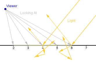
Notice that the viewer's position is the same. The viewer might look at different parts of the surface, viewer sees the specular reflection in only the area where the reflected light would be shining directly towards the viewer.
So, some part of the light is absorbed by the surface and reflected in an arbitrary angle. Another part is directly reflected from the surface. If the directly reflected part would be 100%, then we would have a perfect mirror.
In reality we would have to take into account also the reflected indirect light, but for a simple model we account only for the direct light. This will produce a specular highlight that is sort of a reflection of the light source.
But how to calculate that? Let us have a more concise drawing in order to find that out.
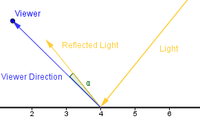
As you can see, there are two vectors: the direction towards the viewer; the direction of the reflected light. If those vectors are pointing in the same direction, then our fragment (number 4) should be more illuminated. In order to determine if they are pointing in the same direction, we can look at the angle between them. If the angle $\alpha$ is 0, then they are. If the angle differs from 0, then they are pointing in different directions. Now, if the angle is really small, then we still have to illuminate the fragment a bit, because real life surfaces are not ideally flat and light sources have some finite area as well.
So, we need a some kind of way to illuminate based on the angle between the viewer direction and the reflected light. Bui Tuong Phong thought in 1975 that a good enough approximation would be to use the cosine of that angle. Assuming that the vectors are normalized, we can find the cosine by just taking the dot product again. If the vectors are not normalized, then we have to normalize them first.
Now, the cosine function is 1, when the angle is 0. It is also symmetric and becomes 0 when the angle is at 90°. We already saw a good use of that in the diffuse reflection case. However, because the cosine decreases so slowly, it would produce a really big and spread out highlight on the surface. Phong proposed to take a power of the cosine. Taking the power causes the cosine to decrease more rapidly, while still preserving the value 1 at 0 and the overall shape. The exact value of the power is left to the programmer and is called the shininess value.
So the overall formula would be:
$red = M_{ambR} \cdot L_{ambR} + M_{diffR} \cdot L_{diffR} \cdot \max(normal \cdot light,\;0) + M_{specR} \cdot L_{specR} \cdot (\max(refl \cdot viewer,\;0))^{shininess}$
$green = M_{ambG} \cdot L_{ambG} + M_{diffG} \cdot L_{diffG} \cdot \max(normal \cdot light,\;0) + M_{specG} \cdot L_{specG} \cdot (\max(refl \cdot viewer,\;0))^{shininess}$
$blue = M_{ambB} \cdot L_{ambB} + M_{diffB} \cdot L_{diffB} \cdot \max(normal \cdot light,\;0) + M_{specB} \cdot L_{specB} \cdot (\max(refl \cdot viewer,\;0))^{shininess}$
This is the Phong's lighting model. It includes the ambient term, Lambertian / diffuse term and the Phong's specular term. There are 2 colors for each of those terms: color of the light and the material. So all and all 6 colors. There are also 4 vectors that indicate directions towards: surface normal; light; reflected light; viewer. Those vectors should all be normalized.
As for the behavior of the Phong's specular highlight, consider the example on the right. You can see that when the shininess is 1, then the specular highlight is really big and does not look good. You can also see that it might not be a good idea to use the same color for the specular reflection as the diffuse color. A white specular reflection color gives a more pleasing result. Physically most common materials (except for metals) do not color the specular reflections, thus the specular color should be white. The color slides linearly interpolate between red (left) and white (right).
You can try first increasing the shininess to some higher value. Then move the diffuse color to 0 (red). You can see that the highlight is barely visible. If you move the specular color also to 0 (red), then you can not see the specular highlight, because the are can not get any more red. Move the specular color to 1 (white) to see a white specular highlight.
Blinn-Phong Lighting Model
Another, a bit more realistic, lighting model is the Blinn-Phong model that calculates the specular term somewhat differently.
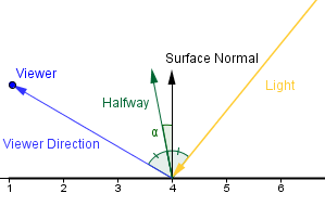
In Blinn-Phong model we are using a halfway vector between the light source and the viewer. This vector will coincide with the surface normal if the reflected light coincides with the viewer direction.
Everything else is the same, but we are now using the cosine of the angle between the halfway vector and the surface normal. The shininess exponent of this is about 4 times times bigger then in Phong's model for roughly the same sized highlight.
Also the highlight will behave a bit differently, when the viewer is looking at a grazing angle towards the surface. The highlight will be more oval-shaped, thus projected circularly, rather than being circular and projected as an oval. This is more realistic (see page 5 for explanation).
You can try this out in the example on the right. First pick a good shininess value and then try to rotate the light's direction. The left sphere has Phong's specular and the right one has the Blinn-Phong specular.
Currently we are using the orthographic projection and a directional light source. This means that the viewer direction and the light direction are always the same for all the fragments. Because of that we can calculate the halfway vector beforehand and send it to the shaders. The halfway vector will always be the same and we do not have to recalculate it in the shaders all the time. We just take the cosine of the angle between the surface normal (which is different) and the halfway vector (which is the same).
This kind of optimization could not be done with the Phong's model, because the reflected light would have been in a different direction all the time and we have to recalculate it for each fragment. Alas it will only work here if the light source and viewer are considered to be in infinity (e.g. directional light, orthographic projection).