Introduction to Geometry
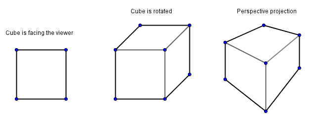
Geometry is quite an important thing in computer graphics. As mentioned before, computers mostly know how to do math. Geometry is a field in mathematics that allows us to describe the physical layout of our every day world. We can describe it in 3 spatial dimensions, usually denoted as $x$, $y$ and $z$ directions. We can also describe some things in 2 spatial dimensions. One idea would be that 2 spatial dimensions describe a drawing on a paper or a photograph. That is kind of true, but those mediums carry additional information: lines in the drawing; color values in the photo. If we are talking about geometry only then we can only talk about geometric concepts like points, lines, polygons etc. A cube in 3D can become a square in 2D. I say can, because depending on the orientation and a projection from 3D to 2D we use, this might vary.
In the introductory chapter we mentioned how a geometrical space can be constructed. We need an origin point and some vectors that serve as the basis. If we are constructing a 2D space, then we use 2 basis vectors, if it is a 3D space, then 3 basis vectors. All points in that space are represented via a linear combination of those basis vectors.
Given a constructed Euclidean space, it becomes a bit tedious to distinguish between points and vectors. There is a notion of homogeneous coordinates that goes one dimension higher than our previously constructed space. If the value of the extra dimension is 0, then we are dealing with a vector. Any non-zero value in the extra dimension will denote some point in the original space. We will come back to this at a later stage. Key thing to remember is that both points and vectors can be represented in a one dimension higher space in homogeneous coordinates.
Here are some definitions:
- Point – set of values that denotes a location in a space. Example $(1, 1)$, in homogeneous coordinates $(1, 1, 1)$.
- Vector – set of values that denotes a direction in a space. Example $(1, 1)$, in homogeneous coordinates $(1, 1, 0)$.
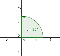
- Orthogonal vectors – perpendicular vectors, angle between them is 90°.
- Line – set of points that satisfy a linear equation of two variables. Example $x + y = 2$.
- Line segment – part of a line that is bounded by two distinct points.
- Plane – set of points that satisfy a linear equation of three variables. Example $x + y + z = 2$.
- Dot product – also called scalar product and inner product. $v \cdot u = |v| \cdot |u| \cdot cos(∠uv)$.
Coordinate Systems
Although we could define a space with any three linearly independent basis vectors and an origin, it is preferable to use an orthonormal basis. This means that the basis vectors are of length 1 and orthogonal to each other.
This actually also leaves quite a few possibilities that need to be distinguished. Usually in computer graphics we want to know, which way is up-down, which way is left-right, and which way is forward-backward. This allows us to always position the objects in a correct way. For example let us say that we have defined a space (usually called the world space) with an orthonormal basis. We would like to be able to say that our main character has moved 3 units to the left and 4 units up from the origin in the world space. How do we say that?
Maybe some of those: $(3, 4)$, $(4, 3)$, $(3, -4)$, $(-3, 4)$, ...
Depending on the way we have defined our basis vectors, any one of those guesses can be correct. So people have tried to come up with some conventions and agree upon their use.
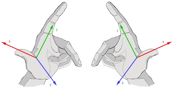
We can distinguish a left-handed or a right-handed coordinate system. Difference between those is the directions of the basis vectors. We have the vectors that are orthagonal to each other, but their directions can vary.
Usually we want to use the right-handed coordinate system. This will also fix the positive angle to be in the counter-clockwise rotation. The positive angle is the angle from x axis to y axis, when you are looking from the positive direction of the z axis.
This is all good, but would still leave us with some possibilities for our problem of moving the main character.
Only those possibilities left: $(-4, 3)$, $(4, -3)$, $(3, -4)$ and $(-3, 4)$.
We also need to define, which directions in our space, denote the directions we want. In OpenGL and usually in other programmer related software, it is so:
Left-right - x axis, with positive direction as right
Up-down - y axis, with positive direction as up
Forward-backward - z axis, with positive direction as backward
In 3D modelling software it might not always be like so. Sometimes the y axis could mean forward-backward and z axis up-down direction.
So, in order to move our main character 3 units to the left and 4 units up from the origin, the new coordinate would be $(-3, 4)$.
Orthogonalization.
We will see later that actually in computer graphics we are using many coordinate systems and always transforming them. For example if we turn our camera around the up vector, the coordinate system centered on the camera (camera space) has the left, backward vectors changed. Because we can hold floating point numbers only up to a certain precision, some error is bound to happen. If that error accumulates over time, it might be that our once orthonormal basis is no longer orthonormal. In that case we would need to orthogonalize and normalize it again.
Given three vectors, one can make them orthogonal using the Gram-Schmidt orthogonalization process.
Before we see Gram-Schmidt's process however, let us see what does the dot product of two vectors gives us when the second vector is normalized (has length 1).
$u \cdot v = |u| \cdot |v| \cdot cos(∠uv) = |u| \cdot cos(∠uv)$
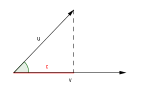
But what exactly is $cos(∠uv)$? We can find the answer by writing out the definition.
$cos(∠uv) = \frac{c}{|u|}$
If we substitute that back to the dot product:
$u \cdot v = \frac{c \cdot |u|}{|u|} = c$
So we get the length from the start of the vector $v$ to the projection of $u$ onto $v$.
This is called a scalar projection and it is the first indicator that the dot product has some really interesting and useful applications.
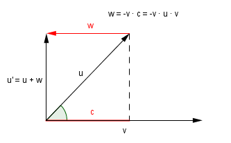
Now, to Gram-Schmidt process. Assuming that we have those same vectors $u$ and $v$. We want to make $u$ orthogonal to $v$. From the image above, we can see, that this can be accomplished if we just add to $u$ a vector of length $c$ and a direction opposite of $v$. Or in other words, we can subtract $c \cdot v$ from $u$.
This is actually the main step in Gram-Schmidt. We pick one vector that will serve as a starting point. This vector will stay the same (currently it is $v$).
Next we do a scalar projection of the second vector onto the first vector to find the length needed to be corrected.
$v' = v$
$u' = u - v' \cdot u \cdot v' $
The preceding steps will be similar, but now we have to use more projections. For example if we would have vectors $u_1, u_2, u_3$ then $u_2$ will be corrected based on $u'_1$ like before. But $u_3$ will be corrected based on both $u'_1$ and $u'_2$.
Keep in mind that the scalar projection only works if the vector we are projecting onto has unit length (is normalized). In order to normalize a vector, you have to divide it by its length. $u_{norm} = \frac{u}{|u|}$. So it would be good to actually normalize $u'_1, u'_2, ...$ when they are found, because they will be used in subsequent steps.
Points and Vectors
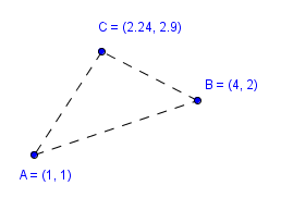
We have already discussed the difference between points and vectors. As also mentioned, points will define specific locations in the space. For example you can have 8 points that define vertices of a cube. The most common use of points in computer graphics is to define vertices of a polygon, usually a triangle. We will see this more when we discuss polygons. Of course there are some cases where you would actually want to define just a point. For example in the case of particle systems, where you have a set of points that act according to some rules. You might then decide to draw those points as single pixels or perhaps use some image that is centered in those points. We will see more examples of this later in the course when we look at procedural generation.
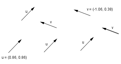
As for vectors, these are the main component in lighting calculations. When we have some polygons in our space, we can define a directional lighting and color the polygons according to the angle they face the light's direction. Usually we want our vectors normalized, because this will simplify and allow for more interesting calculations. One example we already saw with scalar projection, the vector we projected onto had to be normalized for it to work correctly.
In homogeneous coordinates we can distinguish between those easily. We will see the reasons for it when we look at the transformations. For now, remember that in homogeneous coordinates:
Point - $(x, y, z, w) = (x/w, y/w, z/w)$ where $w \neq 0$.
The relation between the 4D homogeneous coordinates and the corresponding point in 3D. Usually you want to use $w = 1$.
Vector - $(x, y, z, 0)$. We can also think of this as a point located at infinity.
Polygons
We mentioned how points can define the vertices of polygons. This is true, but it is important to know that in 3D if we define 2D polygons, then those polygons have two faces (sides): the front face and the back face. 3D shapes are usually formed of many 2D polygons that can be connected into a single mesh. This way a larger shape will share the vertices and edges of many smaller shapes. If we actually want to do this all the time, depends on our shape and how are we using it.
Coming back to the faces of a polygon. Imagine that we have a 3D cube that is made up from 6 2D squares. Those squares can be defined by either 8 points if the adjacent squares are sharing the vertices, or 24 points if they are not. In either way, GPU will rasterize those polygons based on your screen resolution. This means that the vertices from 3D space are projected into your 2D screen and then all pixels in the convex hull of this polygon are colored with some color. We can say convex hull here, because a square is a convex polygon.
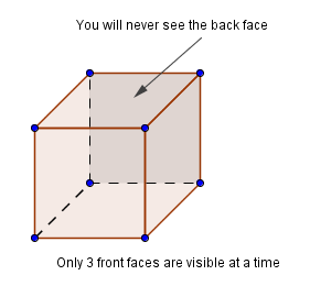
However, when you think about it, only 3 faces of a cube can be visible after a projection onto a 2D screen. So the GPU has to know somehow which of the faces are visible and which are not. This is why we have a front face and a back face. When we are talking about a 3D shape (like the cube), then you would want the front faces to look outward and back faces to look inward. If the cube is meant to be solid, then the camera will never go inside the cube and those faces inside will never have to be rasterized, rendered. This is called back face culling and is usually turned on in the GPU.
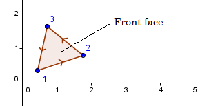
So, how does the GPU know which faces are front and which back faces? This is determined by the order you send your points to the GPU. Because we are using the right-handed coordinate system and our positive angular direction is counter-clockwise, then the vertices are assumed to be in a counter-clockwise order. This determines two sides of the polygon. Front face is the one, where vertices can be read from a counter-clockwise order and back face is the one, where vertices are in the clockwise order.
If you are looking at a polygon from different sides, then the order of vertices is read differently. Imagine looking at the triangle on the right from the opposite side.
Now, you could possibly send the vertices in any random order and even more, the convex hull might cover points that are not actually inside your polygon. This might cause some weird behavior and because of that is not allowed. Nowadays, all that GPU allows you to send, are triangles. Those simple polygons have some nice properties:
- All points are always on a plane - thus there is a single geometrically correct surface normal;
- It is always convex - polygon is exactly covered by a convex combination of the vertices;
- It is always simple - none of the edges intersect each other;
We just mentioned some different definitions here, that you might not be familiar with. Let us try to explain those a bit more.
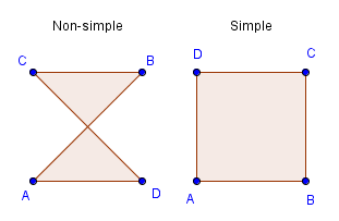
A simple polygon is a polygon that has no edges that cross each other. As you can see, a triangle and a square are simple polygons. You could however define the vertices of a square in an order where the result would not be a simple polygon.
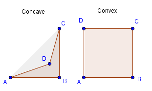
As for convex vs concave, there are several definitions. You could say that a convex polygon is such that contains each line segment that connects any two points inside it. So if you are able to pick two points inside a polygon and a straight line between them will take you outside the polygon at some point, it is not convex, but concave.
You could also say that the polygon is itself's convex hull. Or the convex hull is exactly the polygon itself. Or that the convex combination of the vertices covers the polygon exactly.
On the right there are a couple of examples how 4 vertices can define both non-simple and concave polygons. Both of which are impossible to construct with 3 vertices. Only a convex and simple triangle is possible given any 3 vertices. Like mentioned, that is one of the reasons why in the end GPU only accepts triangles.
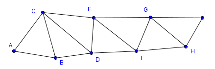
| Triangle strip | Triangle fan |
|---|---|
 |
 |
As you can see, with the triangle strip it would seem that some triangles are in the counter-clockwise and some are in the clockwise order. Actually OpenGL will not flip the triangles in this construction. This means that either all are parsed in a clockwise or all are parsed in a counter-clockwise order. Depending on the first triangle.
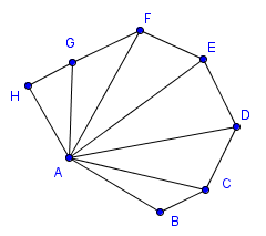
With a triangle fan, there is an important property that all convex polygons can be converted to triangles using it.