Ray Tracing and Space Partitioning
So far we have rendered our scene via the standard graphics pipeline. That is, we sent the geometry to the GPU, where it was rasterized and each fragment colored. Fragment coloring took into account the light source, material properties and used some lighting model to calculate the color value. The scene was drawn from the geometry to the pixel values.
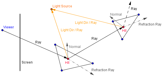
There is another approach that tries to render from the pixel values to the geometry. It is computationally much more expensive, but may allow for some more realistic effects to be easily achieved. The idea behind ray trace rendering is that for each pixel we send a ray to the scene. This ray starts from the viewer location and goes through the pixel we want a value for. Then we need to find out what geometric object ray hits first and the actual hit point. We can calculate a color for that hit point using a lighting model the same way as before. Although it might be more clever to cast another ray from that hit point to the light source, to see if the light is actually visible. Furthermore, we can reflect the ray from the hit point and repeat the process, in order to model reflective materials.
The majority of the computations here will go into determining what object a ray hits first. If we have objects consisting of triangles, then in the simplest approach we need to calculate ray-triangle intersection testing for each ray for each triangle. This can become really slow. There are many data structures that can improve this by organizing the triangles in a way, where we can determine which triangles might be on the ray's path, and which are certainly not.
We will be looking at the idea of ray casting, ray tracing and those data structures.
Some definitions:
- Ray – a mathematical object that has an origin and a direction.
- Ray casting – technique of constructing a ray and finding out what it intersects.
- Ray tracing – technique of doing ray casting recursively, reflecting the rays as they hit the geometry.
- Data structure – way of organizing the data so, that some operations are effective (usually have a lower complexity class)
- Spatial indexing – way of organizing the spatial data so that spatial queries are effective.
- Tree – an hierarchical data structure, acyclic and connected graph with one of the nodes classified as a root.
Ray Casting
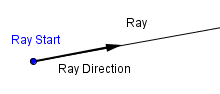
We can define a ray as a following equation.
$Ray(t) = Start + t \cdot Direction$
Here the parameter $t$ will denote how many times the $Direction$ vector we have traveled along the ray. If we have implicit geometry, which means that we have equations to test if a point is inside a geometric object, then we could try to sample along the ray with some step size and see if we have passed the object's surface yet.
Currently, however, we have constructed our geometry from vertices and triangles. We mentioned that all vertices of a triangle always lie on the same plane. This means that given a triangle, we can also get a plane, where it lies. In other words, a triangle will actually form a plane. In order to see that, let us look at a triangle with vertices $v_0$, $v_1$ and $v_2$.
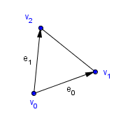
We can form a 2-dimensional vector space, ie a plane, by taking $v_0$ as the origin and vectors $e_0 = v_1 - v_0$, $e_1 = v_2 - v_0$ as the basis vectors. They are definitely linearly independent vectors, otherwise we would not have a triangle, but a line segment. We can represent coordinates in this triangle-based plane with letters $u$ and $v$. These are called barycentric coordinates. It is easy to see that the points inside the triangle must be in a convex combination of $e_0$ and $e_1$. Notice, that this is not a orthonormal basis, the basis vectors are not normalized, nor are they, in general, orthogonal.
So the triangle itself would be:
$Triangle(u, v) = u \cdot e_0 + v \cdot e_1 + v_0$,
where $u \geq 0$, $v \geq 0$ and $u + v \leq 1$.
Now, a ray will intersect a triangle, if there will be such $u$, $v$ and $t$ that, in addition to the previous conditions, satisfy:
$Ray(t) = Triangle(u, v)$
This means that there will be a distance $t$ we can travel along the ray, such that we get a point in the triangle. That point has the barycentric coordinates $u$ and $v$.
In order to find if such parameters exist, we need to solve the system of equations. Let us denote the $Start$ and $Direction$ of the ray as $s$ and $d$.
$s + t \cdot d =u \cdot e_0 + v \cdot e_1 + v_0$
Because we are in 3D space, we actually have 3 equations.
$s_x + t \cdot d_x =u \cdot e_{0_x} + v \cdot e_{1_x} + v_{0_x}$
$s_y + t \cdot d_y =u \cdot e_{0_y} + v \cdot e_{1_y} + v_{0_y}$
$s_z + t \cdot d_z =u \cdot e_{0_z} + v \cdot e_{1_z} + v_{0_z}$
For simplicity, we can just write the one equation and keep in mind, that we are dealing with 3-dimensional vectors. The first thing we do, is move the variables to one side:
$t \cdot d - u \cdot e_0 - v \cdot e_1 = v_0 - s$
This can be written as a matrix-vector equation:
$ \left( \begin{array}{cc}
d & -e_0 & -e_1
\end{array} \right)
\left( \begin{array}{cc}
t \\
u \\
v
\end{array} \right)= v_0 - s$
Next we will be using the Cramer's rule to try and find a solution. Now, the Cramer's rule is only valid, if the system actually has a single solution. It might happen that we have no solutions (ray does not intersect the triangle) or infinitely many (ray goes along the triangle). We have to test those cases out.
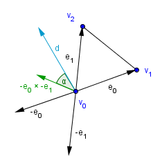
If $ \begin{vmatrix} d & e_0 & e_1 \end{vmatrix} = 0$, then there is no solution and we do not have to even look further. For calculating this determinant, we can use a scalar triple product. That will tell us that: $ \begin{vmatrix} d & -e_0 & -e_1 \end{vmatrix} = d \cdot (-e_0 × -e_1)$. You can think about this geometrically, $-e_0 × -e_1$ will give us a vector that is perpendicular to the plane formed by the triangle. If the angle between that vector and $d$ is 90° or 270°, then the cosine will be 0, the dot product will be 0, and the determinant will be 0.
If the determinant is not 0, then we know that the ray will intersect the plane formed by the triangle. We still do not know, if it will intersect it inside the triangle. For that we need to find out $u$ and $v$ and see if the conditions for them hold. Using the Cramer's rule, we will get the following equations:
$
\left( \begin{array}{cc}
t \\
u \\
v
\end{array} \right) = \dfrac{1}{
\begin{vmatrix}
d & -e_0 & -e_1
\end{vmatrix}
} \cdot \left( \begin{array}{cc}
\begin{vmatrix} v_0 - s & -e_0 & -e_1 \end{vmatrix} \\
\begin{vmatrix} d & v_0 - s & -e_1 \end{vmatrix} \\
\begin{vmatrix} d & -e_0 & v_0 - s \end{vmatrix}
\end{array} \right)
$
The values can be calculated quickly with the scalar triple product, like before.
$
\left( \begin{array}{cc}
t \\
u \\
v
\end{array} \right) = \dfrac{1}{
d \cdot (-e_0 × -e_1)
} \cdot \left( \begin{array}{cc}
(v_0 - s) \cdot (-e_0 × -e_1) \\
d \cdot ((v_0 - s) × -e_1) \\
d \cdot (-e_0 × (v_0 - s))
\end{array} \right)
$
It is possible to rearrange the values so that we need to calculate only 2 cross products. Next we can find out the value for $u$. If $u \leq 0$ or $u \geq 1$, then the ray will not intersect inside the triangle. Otherwise, we can proceed in finding $v$ and testing if $v \leq 0$ or $v+u \geq 1$. If those are true, then the ray will not intersect either. Otherwise we can calculate $t$ and see if $t > 0$, in which case we have determined the hit point to be $t \cdot d$.
This is called the Möller-Trumbore intersection algorithm for finding ray-triangle intersections. If you read their paper, then you can see how to rearrange the values more optimally. You can also do back-face culling quite early on. If the determinant is less than 0, then the ray is approaching from the back-face and you can qualify it as a miss.
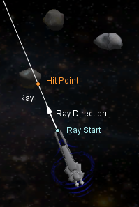
You can use ray casting and intersection testing for all sorts of things. For example, you can calculate what a laser beam or a bullet (with a relatively straight trajectory) hits. The mouse control in the Curves topic was done by casting a ray into the scene from the mouse coordinates.
In the image on the right there is a space ship that determines which asteroid it is pointed at via casting a ray from its nose in the direction it is facing.
Although, as mentioned, doing the ray-triangle intersection for a scene that may have hundreds of thousands of triangles, can be really expensive.
Ray Tracing
One way to render a scene is by casting rays from the viewer through each pixel we need a color value for. For each ray, we can find, which triangle it intersects first. On the hit point, we can calculate the color via some lighting model. If the surface is reflective, then we can reflect another ray from the hit point and take into account the color value it receives by some reflectivity coefficient.
$color = 0.5 \cdot color + 0.5 \cdot rayCast(hit, reflectedDirection)$
This is a recursive process and needs to terminate after some number of bounces. The actual coefficients will probably become way too small to visually affect the result as well.
Besides reflecting a ray, there can also be refractive materials. Instead of a mirror sphere, you could have a glass sphere, that will let light pass through, but change its direction a bit. So you might want to cast another ray inside the geometric object. Although in that case you do not want to do back face culling for the ray-triangle intersection. Light will change direction whenever the material it passes through changes in density. So when the ray exits the glass sphere, it should change the direction again.
On the right, there is an example of the Cornell Box scene. The example might be a bit slow because I am not using any special data structures to hold the triangles. For each ray, intersections for all of the triangles are tested. You can also add a mirror sphere to the scene and have it move around.
For light calculations only the direction of the light source is taken into account (no rays are cast towards the light source). There is a single point light source located in the ceiling. The scene looks almost identical to the one that can be rendered via the standard graphics pipeline. Except that for the reflective sphere we would need to use some environment mapping.
Space Partitioning
Space partitioning is a concept of dividing the space into a number of parts recursively. There are several ideas on how it is best to divide the scene. I find that different space partitioning ideas are best demonstrated in 2D, but for a moment, let us consider that we have a 3D scene. The whole scene is kind of empty except for a complicated object in the center of it. Let us say that we are doing ray tracing to see what is in our scene.
Each ray will have to test the intersection with all of the triangles in the complicated object.
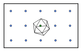
Here it will mean that 15 rays will test the intersection with the icosahedron that has 20 faces (ignoring back-face culling, maybe it is a refractive icosahedron). So we run the intersection algorithm 300 times.
What we could do is divide the scene into boxes and say that a triangle will be in a box, when some of its vertices are in it.
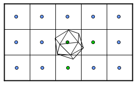
Now, for all of the rays, we will first find the box it will intersect. Currently there is just a grid of boxes, so we would need to test each ray for all of the boxes. If there are 15 boxes, then we will do 225 tests to find where the ray goes, then we do 20 intersection tests for the middle ray and some 3 or so intersection tests for 2 other rays (one box below and one box to the right of the middle box). This means 251 tests in total. Not much progress, although if we would have more geometry in the scene, then there will be more gain.
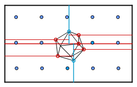
This kind of equal distribution grid-based approach has many problems. First we assume that the rays always intersect only one box. If the boxes are not aligned with the ray direction, then this may not be the case. Secondly, we are generating lots of empty boxes, when in reality we could have less of them.
Let us address the second problem first. We could divide our space into 4 (or 8 if we consider the depth dimension) boxes. If there are a number of vertices in the box, we can recursively divide it again into smaller ones. This is called a quadtree or an octree.
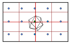
It is not that visible from here, but currently each ray would do 2 tests to find out which box they fall into. Then only 3 rays that have a chance to hit the icosahedron, actually do the triangle testing. Those rays actually test only about 5 triangles each. So we have 45 tests. Imagine if the icosahedron would be on the left side of the scene. In that case we would not have to divide the boxes on the right side, and those rays would only do 1 test to find out their box.
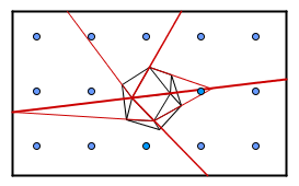
Another way to partition a scene would be to use a K-D tree. There we will divide by the median value in each dimension alternatively. So first we find the median of x-coordinates for all the vertices and split the scene in half along the axis. Then recursively we find the median y-coordinates in both partitions.
When traversing the tree, we will find which side of the separating hyperplanes (just normal planes in our 3D case) the ray will be.
Instead of constructing those planes, we could use the planes already existing in our geometry. Just pick one polygon and divide the scene into half (those on the front side of that polygon and those on the back). Recursive repetition of this process will generate a similar structure, but now we are not restricted to our axes. This is called binary space partitioning.
Each of those have some benefits, some problems and there are a lot of more structures for spatial indexing.
As for the other problem, when our structure is not aligned with the rays. Well, if we are in 3D, then our structure will also be a 3D structure. If we are passing a ray through the scene, then we need to pass it through the structure. So for example, with a quadtree, we would need to determine the cell the starting point is. After that we will see which neighbouring cell the ray hits and move to that one. We continue until we can find a closest intersection.
For a more interactive demo, check out the NNS algorithm visualization.
Bounding Volumes
Another quite simple approach would be to just surround complex objects with simpler ones to use with rays. Imagine if we had a cube around our icosahedron.
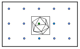
All rays would test the intersection with that cube. Only the middle ray would pass it and continue with the triangles. So we would have 15 tests with cubes and then 20 tests for the middle ray, in total 35 tests.
With more complex scenes we can group together several close objects and create a bounding volume hierarchy.
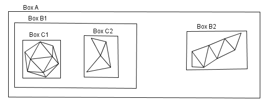
Usually the bounding boxes are axis-aligned and called AABB. There are faster algorithms to find the intersections for those than for an arbitrary bounding box.