Ray Chopper
You have probably seen the ray trace based rendering example under the materials here. In this task we will be implementing something quite similar ourselves.
We can imagine that there is a plane in front of the camera through which we shoot rays originating from the camera. Whatever that ray hits should be projected onto that plane. The plane is then considered to be what we actually see on the screen.
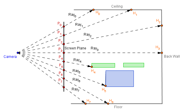
In order to generate that Screen Plane, we could just create a quad and an orthographic camera that will be looking at it. This will create an environment, where we we run the fragment shader for each pixel on the screen. Remember, normally the fragment shader would be run for each rasterized fragment of the objects. Now we want the fragment shader for all pixels regardless of the objects and we also do not want any distortive projection (thus we use orthogonal projection).
Then the vertex shader will give us the vertices of the plane, which are the vertices of the quad that covers the screen / viewport. If we interpolate those vertices to the fragment shader, then we get different fragment coordinates on the the plane. Thus, in the fragment shader we have the points that a ray from the camera should pass, and we can also fix the location of the perspective camera. This will define a ray with a start point and a direction. Using those we could think of the ray as:
$Ray = Start + t \cdot Direction$
Next we would need to know, what the ray actually hits in our scene. Because our scene consists of triangles, we can use Möller-Trumbore ray-triangle intersection algorithm to test each ray against all the triangles.
When we have found the triangle with a closest hit point, we can calculate the exact coordinate by the $t$ (how much of the direction we should take from the start to get to the hit point) value that the algorithm outputs. In that hit point we can calculate some light, for example diffuse and ambient, and that would be the output of the fragment shader.
So, the fragment shader will need the following data:
- Vertices of the triangles in world space (these can change)
- Face indices of the triangles
- Normals of the faces in world space (these can change)
- Colors of the faces in world space (these can change)
We will be using flat shading here, which mean that there will be a single color per triangle. It would also be possible to do other shadings. For Phong (per-fragment) shading we would just store the normals for each vertex and use the Barycentric coordinates to interpolate them for a hit point. But currently, flat shading would be more easier to just try things out.
The face indices we can send directly to the shader as a ivec3, but the other three values could change each frame. There are other ways to do this, but currently we will be sending those values as data textures. They will just be textures that us ourselves have created and stored values in. Textures have a possibility to store 3 or 4 values per texel (cell). We will be using the usual 3 values per texel.
The vertex positions in world space we can send as a texture with one row. Instead of the three color channel values, we will keep the three coordinate values in the texture.

Faces have two attributes assigned to them, a normal and a color. We have a different number of faces then vertices, thus we need to create another texture. This one will have two rows.

In the fragment shader we will basically:
- Loop through the face indices array
- Sample the vertex texture with the index values to get the coordinates of a triangle
- Find the current ray intersection with that triangle
- On success, we sample the faces array with the index of the current triangle to get the face attributes
Most of that has been done in the base codes, but there are key steps that you can fill in. :)
Base codes have comments in them that indicate the missing pieces. One thing to note is that in both of the base codes we are compiling the shaders for a fixed number of vertices and triangles. This is because in GLSL you can not have a loop that has a variable stop value. Only loops that know exactly how many iterations they maximally do on compile time.
Both base codes initially give you some errors, because some of the variables are uninitialized etc. Also, if running the algorithm is slow, then you can decrease the viewport size. If it is fast, then increase the viewport size and see how many rays can you trace before performance becomes an issue.
JavaScript
You should get a similar result to this with the blades rotating:

Three.js has a THREE.DataTexture class, which you might want to read about. We will be using that.
Base code is located at:
https://cglearn.codelight.eu/files/course/13/RayChopperJS.zip
C++
The result you should get is very similar to before (it is a bit larger, because the viewport in C++ base code is a bit larger):

In here we will use the glTexSubImage2D() command, which you might want to read about. It seems that from OpenGL version 4.5 there is a bit neater glTextureSubImage2D() command also available.
Base code is located at:
https://cglearn.codelight.eu/files/course/13/RayChopperCPP.zip